How to Calibrate Your CNC Router for Perfect Dimensional Accuracy
One of the most frustrating experiences for a CNC operator is finishing a job only to find that the final dimensions are off by a fraction of a millimeter. In industries where precision is paramount, “close enough” isn’t good enough. To ensure your CNC router parts perform at their peak, regular calibration is essential.
In this guide, we’ll walk you through the critical steps of calibrating your CNC router to achieve and maintain perfect dimensional accuracy.
1. Squaring the Machine (Gantry Alignment)
Before you touch any software settings, you must ensure the machine’s geometry is correct. If the X and Y axes are not perfectly perpendicular, every rectangle you cut will be a parallelogram.
- The 3-4-5 Method: Use a large square or the Pythagorean theorem (3-4-5 triangle) to check for squareness.
- Adjustment: Loosen the gantry mounting bolts slightly, adjust the position until perfectly square, and retighten. For dual-motor Y-axes, ensure both motors are homing to identical positions.
2. Calibrating Steps Per Unit (Scale Calibration)
The “Steps Per Unit” setting in your controller (Mach3, GRBL, etc.) tells the motor how many pulses it needs to move exactly one millimeter or inch. Over time, factors like belt stretch or slight variations in ball screw manufacturing can cause inaccuracies.
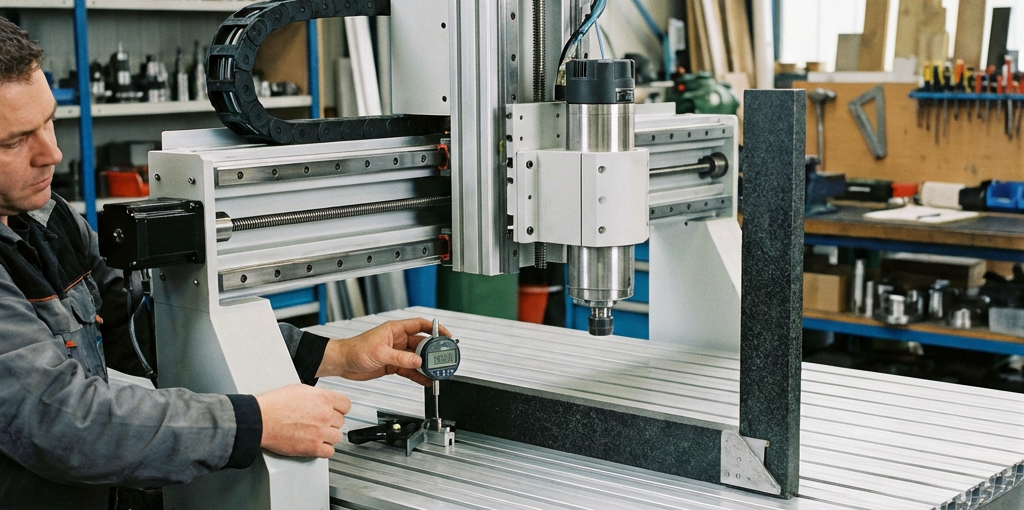
- The Test Run: Command your machine to move 500mm.
- The Measurement: Use a high-quality digital caliper or a dial indicator to measure the actual distance traveled.
- The Formula:
New Steps = (Commanded Distance / Actual Distance) * Current Steps. - Update: Enter the new value into your controller and repeat the test until the error is eliminated.
3. Tramming the Spindle (Z-Axis Squareness)
If your spindle is tilted even slightly, it will leave “ridges” on the surface of your material during pocketing operations. This is known as the “nod” or “tilt” of the spindle.
- Use a Tramming Gauge: A dual-indicator tramming gauge is the most accurate way to check this.
- Surface the Bed: Sometimes, simply surfacing your wasteboard (spoilboard) is enough to reveal tramming issues. If the surfacing bit leaves steps between passes, your spindle needs adjustment.
4. Addressing Backlash
Backlash is the “play” or “slop” in the mechanical system, usually caused by loose drive nuts, worn belts, or loose couplings.
- Mechanical Fix First: Tighten all set screws on your couplings and check the tension of your timing belts.
- Software Compensation: Most modern CNC controllers offer “Backlash Compensation.” While it can help, it is always better to solve the mechanical issue first by using high-quality precision-ground ball screws and anti-backlash nuts.
5. Summary Checklist
| Frequency | Action |
|---|---|
| Weekly | Check for loose couplings and belt tension. |
| Monthly | Verify “Steps Per Unit” calibration on all axes. |
| Quarterly | Re-tram the spindle and check the squareness of the gantry. |
Conclusion
Calibration is not a one-time event; it is an ongoing part of professional CNC operation. By spending 30 minutes each month on these checks, you will save hours of rework and prevent the waste of expensive materials.
Looking to upgrade your drive system for better accuracy? Explore our high-precision ball screws and linear guides to take your machine’s performance to the next level.